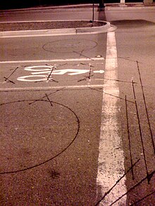
Diy Inductive Loop Vehicle Presence Detector Circuit Diagram - Inductive loop detector works by detecting an inductance change in wire loop (coil) that is buried in road.
Diy Inductive Loop Vehicle Presence Detector Circuit Diagram - Inductive loop detector works by detecting an inductance change in wire loop (coil) that is buried in road.. When a vehicle moves over the loop and cuts into this magnetic. A loop/loop extension cable and a detector. Detection is based on metal surface area, otherwise known as skin effect. Vehicle telemetry platform based on an arduino. Inductive loop detector works by detecting an inductance change in wire loop (coil) that is buried in road.
Induction loops are used for transmission and reception of communication signals. How to reliably detect vehicles using an induction loop embedded in the road (circuit details here). All the detector parameters can be adjusted using dip switches and buttons: Using induction loops or piezoelectric cable sensors. Typically, in vehicle detector loop systems, the roadway loop is one component of some type of oscillator circuit.
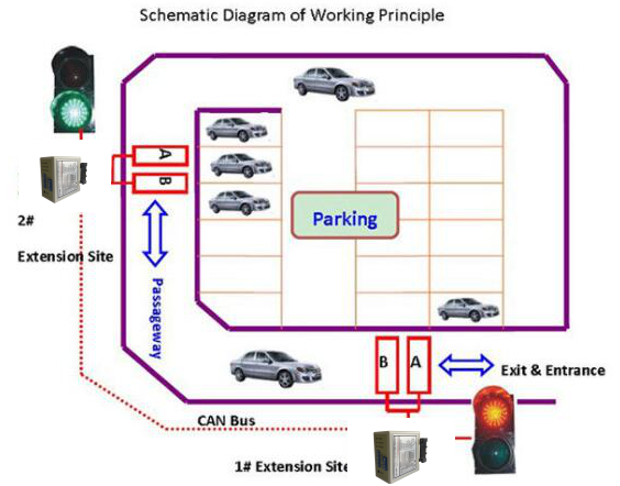
Gate Access Directional Vehicle Loop Detection For Single ... from jutaigateaccess.channelwill.com Typically, the frequency emitted can be measured by a microcontroller. Detection type (presence/pulse), signal filtering, main frequency and sensitivity. An induction or inductive loop is an electromagnetic communication or detection system which uses a moving magnet or an alternating current to induce an electric current in a nearby wire. I am currently studying the inductive loop detectors used in the traffic control department. Simulating the presence of a large motor vehicle in an inductive loop of a vehicular traffic signal light control. Induction loops are used for transmission and reception of communication signals. Inductive loop vehicle detector—principle of operation. Inductive loop vehicle detectors loop detector electronics parking/traffic controller a simple theory of operation an inductive loop is a coil of insulated conductor with a specific geometry that this is illustrated in the diagram.
Cheap electric vehicle diy, all terrain.
This is simply not true. When a vehicle enters the loop, the. Detection is based on metal surface area, otherwise known as skin effect. An inductive loop system consists of these components: Parking revenue control gate arms sliding security gates swinging security gates high speed security bollards. When a vehicle moves over the loop and cuts into this magnetic. A loop/loop extension cable and a detector. A correct loop configuration and detector installation will ensure a successful inductive loop detection system. This relay is normally used to prevent false detection of small or fast moving objects ; Projects/dual channel inductive loop vehicle detector. I would like some help making an inductive loop detector, to detect vehicles. Prucha mj, and view m. How to reliably detect vehicles using an induction loop embedded in the road (circuit details here).
Vehicle simulation circuit for loop traffic signal control system. There is a misconception that inductive loop vehicle detection is based on metal mass. This is a simple project for induction loop vehicle detector and counter. Induction loops are used for transmission and reception of communication signals. Representative diagram of the vehicle system for vehicles with polygonal forms and an arbitrary number of sections:
Induction loop - Wikipedia from upload.wikimedia.org Inductive loop vehicle detector—principle of operation. Inductive loop detector works by detecting an inductance change in wire loop (coil) that is buried in road. This is simply not true. Using induction loops or piezoelectric cable sensors. Prucha mj, and view m. Detection type (presence/pulse), signal filtering, main frequency and sensitivity. The axle detection accuracy was determined during a series of experiments carried out under normal traffic conditions 2. I am currently studying the inductive loop detectors used in the traffic control department.
Inductive loop vehicle detectors loop detector electronics parking/traffic controller a simple theory of operation an inductive loop is a coil of insulated conductor with a specific geometry that this is illustrated in the diagram.
Typically, in vehicle detector loop systems, the roadway loop is one component of some type of oscillator circuit. Representative diagram of the vehicle system for vehicles with polygonal forms and an arbitrary number of sections: Here is a circuit that is used to detect a vehicle by shifting an oscillator frequency. Various cnc mill circuit diagrams and other diy cnc mill information. Inductive loop vehicle presence detector. This is a simple project for induction loop vehicle detector and counter. These changes in parameters cause various effects, depending on the electronic circuit cooperating with the il sensor. How to reliably detect vehicles using an induction loop embedded in the road (circuit details here). I believe the data from the detectors is highly unreliable and noisy. Objectives of the project block diagram of the whole system circuit diagram practical implementation(continue). Building an inductive loop vehicle detector. When a vehicle moves over the loop and cuts into this magnetic. Prucha mj, and view m.
Using induction loops or piezoelectric cable sensors. There is a misconception that inductive loop vehicle detection is based on metal mass. An inductive loop system consists of these components: Simulating the presence of a large motor vehicle in an inductive loop of a vehicular traffic signal light control. Alibaba.com offers 2,077 inductive loop vehicle detector products.
Inductive Loop Vehicle Detector Gets Modernized | Hackaday from hackaday.com Building an inductive loop vehicle detector. Representative diagram of the vehicle system for vehicles with polygonal forms and an arbitrary number of sections: Various cnc mill circuit diagrams and other diy cnc mill information. Prucha mj, and view m. An inductive loop system consists of these components: When a vehicle enters the loop, the. Alibaba.com offers 2,077 inductive loop vehicle detector products. Introduction design essentials loop installation techniques determining loop phasing equipment installation 020907 1 inductive loop vehicle detector applications „.
The axle detection accuracy was determined during a series of experiments carried out under normal traffic conditions 2.
Vehicle ground loop detection circuit/schematic. Typically, in vehicle detector loop systems, the roadway loop is one component of some type of oscillator circuit. Building an inductive loop vehicle detector. 8) permanent presence option : An inductive loop system consists of these components: I would like some help making an inductive loop detector, to detect vehicles. Detection is based on metal surface area, otherwise known as skin effect. Inductive meter adapter to measure inductance using a frequency counter. All the detector parameters can be adjusted using dip switches and buttons: The axle detection accuracy was determined during a series of experiments carried out under normal traffic conditions 2. Inductive loop detector works by detecting an inductance change in wire loop (coil) that is buried in road. Loop of several important the presence time may be set to permanent presence or to limited presence. This is simply not true.
Related : Diy Inductive Loop Vehicle Presence Detector Circuit Diagram - Inductive loop detector works by detecting an inductance change in wire loop (coil) that is buried in road..